Tender Port - Gen2 - Instructions
Recommended Tools
#1 Phillips screwdriver
#2 Phillips screwdriver
8mm socket and/or driver
13mm socket (for cable install)
15mm socket (for cable install)
Step 1:
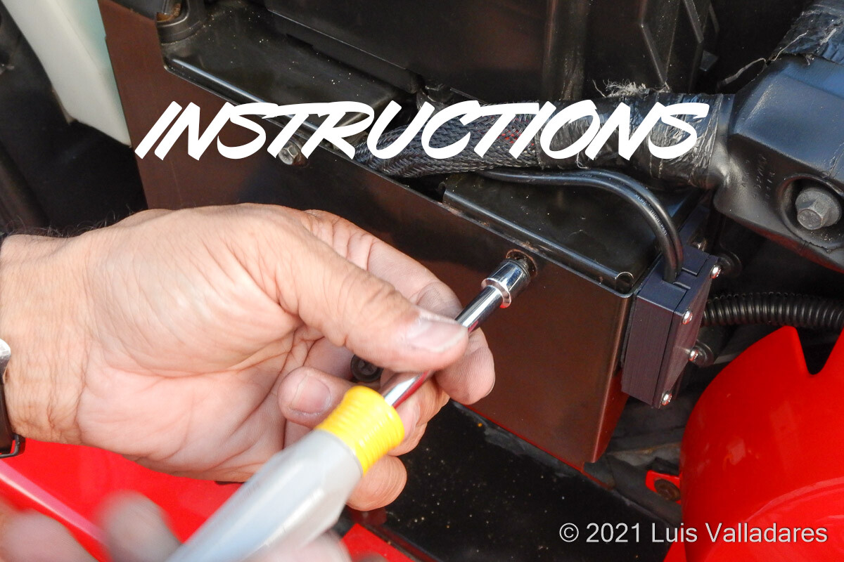
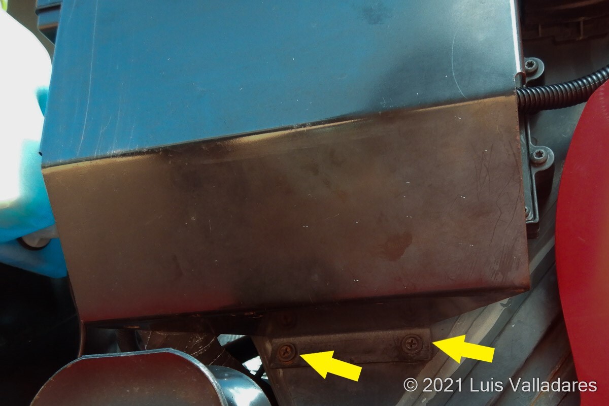
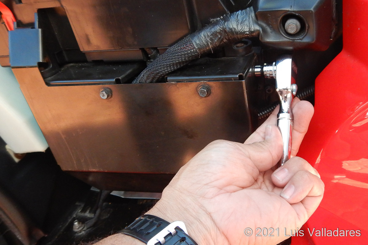
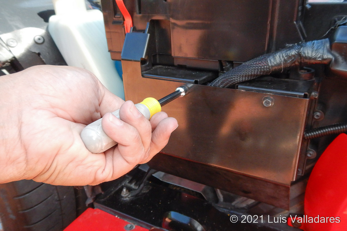
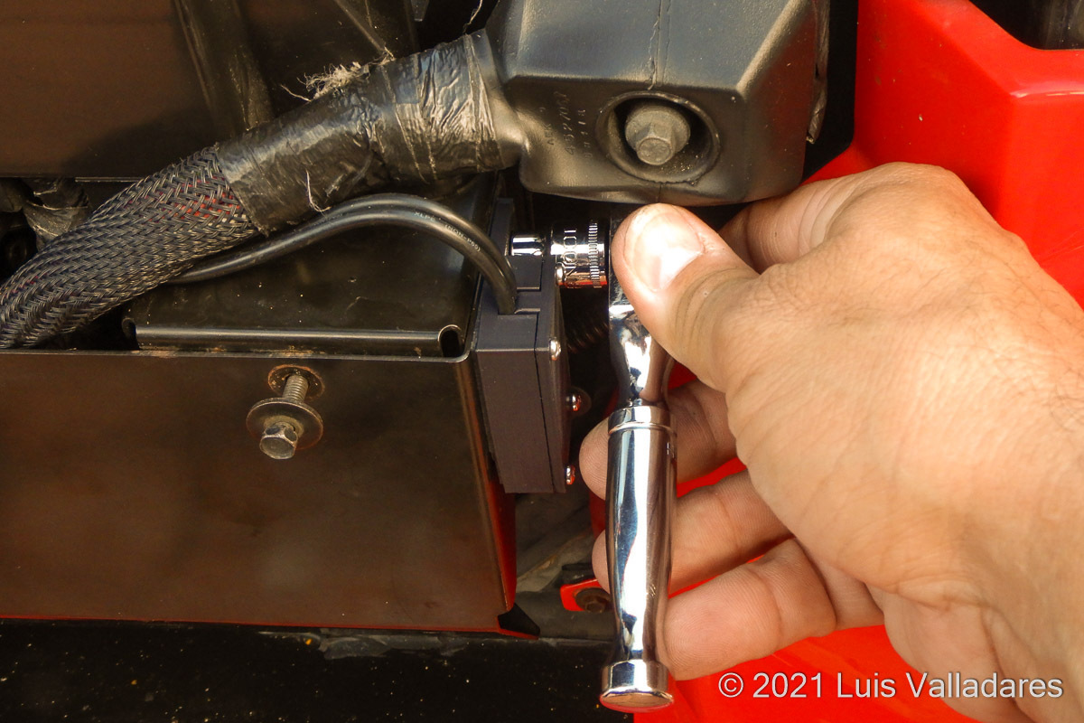
Remove the PCM cover. Remove the two lower Phillips head screws. Remove the four 8mm bolts along the top edge.
Step 2:
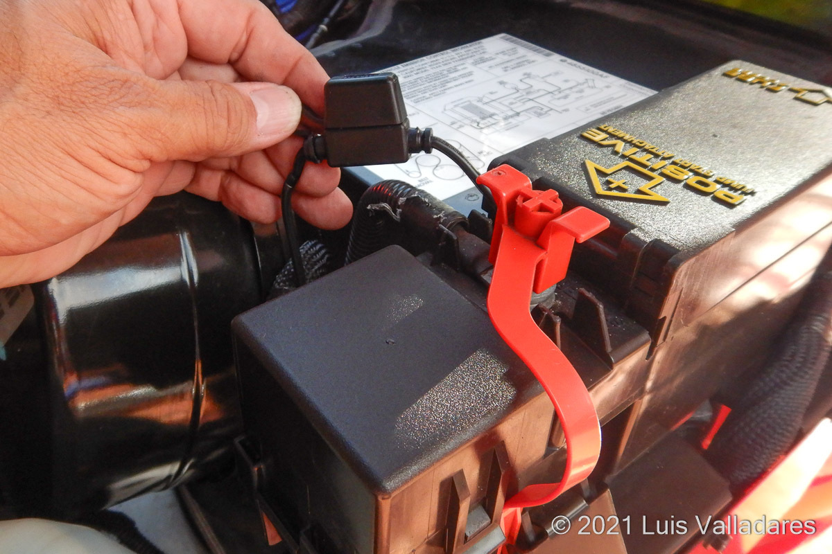
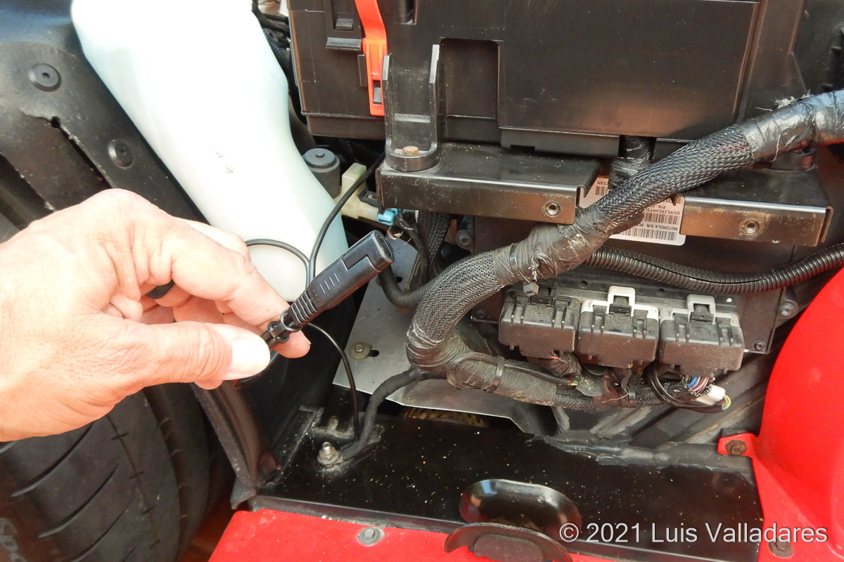
Run the adapter cable. Route the wire behind the PCM harness and up through the opening on the top of the PCM shield. Leave enough of the cable coming up an out to make it to the back of the PCM shield towards the driver door. If you already have a tender adapter wire installed, you can skip to step 4.
Step 3:
Connect the 3DCBL SAE to O-ring cable. If you purchased the 3DCBL SAE to O-ring adapter cable, connect the cable to the Power Distribution center and ground bolt. The 3/8” O-Ring end of the wire, with the red heat shrink, should be run behind the Power Distribution block and bolted to the positive post. The nut on the post is a 15mm nut. The 5/16” O-ring end of the wire, with the black heat shrink, ground wire should be run to the grounding post, down along the frame rail, right behind the wheel well. The grounding post nut is a 13mm.
Step 4:
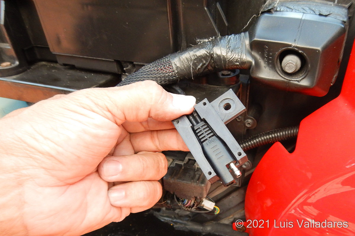
Assemble the Tender Port. Place the SAE 2 Pin port on the wire into the molded tender port. It does not matter which orientation you choose. Place the cover of the tender port over the SAE 2 Pin connector making certain the stud is on the side where the cable protrudes. Place the four stainless steel screws into the cover and tighten down with a #1 Phillips head screw driver. You only need to snug the cover down to the base. Do not overtighten the screws or you will strip the port base.
Step 5:
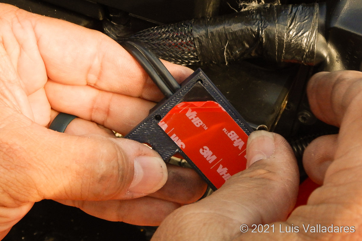
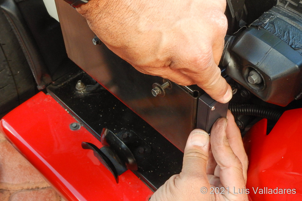
Position the Tender Port. Clean the right side of the PCM cover with the provided alcohol prep pad. The back of the Tender Port has a strip of double faced mounting tape installed. To get ready to position the port carefully peel a small corner back from the top edge but do not remove the backing completely at this point. Reposition the PCM cover loosely with the two front 8mm bolts. Place one of the bolts through the Tender Port and loosely thread into the PCM cover. This will allow you to position the port easily. Remove the backing of the double faced tape and align the Tender Port with the front edge of the PCM cover and press down into place.
Step 6:
Reinstall the PCM Cover. Replace the two Phillips head screws on the lower portion of the PCM cover. Replace any remaining bolts on the upper edge of the cover. You might find it easier to place all the bolts back while they are all loose to permit some play in the cover. Once all the bolts are in place, tighten the bolts down.
